Shop notes · October 28, 2026
“It’s already flat!!”
That was a customer's answer, recently, when I told him the heatsink in his Power Genius XL would be flattened before the new LDMOS transistor went in. A fair point, on its face: it is machined aluminum, it looks flat, and it lies flat against a straightedge. This note is the longer answer. Short version: flat is a number, and the transistor is the one holding the gauge.
Two ways to kill an LDMOS
In our experience, LDMOS failures come in two flavors: voltage and heat. The device makers draw the same line. Ampleon's white paper on its rugged 50 V LDMOS family walks through both. We went looking for published field statistics on the split and found none; the physics of each, though, is well documented.
Voltage
Depending on the load and "the mismatch phase angle, high voltage peaks may occur on the die". Push hard enough and a parasitic bipolar transistor that lives inside every LDMOS structure triggers, which Ampleon says "will lead to nearly instantaneous failure". The die often shows only "a couple of burned fingers". In Ampleon's list the causes start at the load: a mismatch, harmonics not properly terminated, or a device driven into saturation.
Heat
High dissipation "may result in thermal breakdown of the die and transistor. This typically causes complete destruction of the transistor." Short of that, heat spends the device's life: Ampleon plots lifetime against junction temperature, and the hotter the junction, the shorter the curve.
The heat flavor runs straight through the thermal path, and part of that path is set at the bench. Ampleon splits a transistor's thermal resistance in two: junction to case, which "is specified by the device manufacturer", and case to heatsink, which "depends on the material stack used in the circuit design". The rest of this note is about that second number.
Source: Ampleon, Extremely Rugged 50 V LDMOS Devices Capture ISM and Broadcast Markets, white paper, March 2017.
Flat is a number, not a look
A good portion of the engineering calories put into the design of an amplifier is expended on thermal management. The problem it manages is a chain of thermal resistances in series: junction to case, case to heatsink, heatsink to air. Every watt the final stage does not turn into RF has to walk that chain, and the junction runs hotter by every degree each link adds. The transistor maker sets the first link and publishes it. The fans and fins look after the last. The middle one, the interface between the transistor's flange and the heatsink, is set at the bench, each time a device goes down.
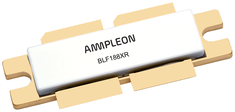
That interface is where "already flat" comes apart. Ampleon, one of the major makers of RF power transistors, writes that bare metal-to-metal contact "could be ~ 2 % depending on the roughness". Bolting the device down raises that, and the gaps that remain are filled with air, aka "a bad heat conductor". Thermal compound fills them, but only as a thin, even film: Ampleon warns that too much "adds a 'layer' of thermal resistance". A thin film needs a flat surface to sit on.
And how flat is flat? NXP's design limit in AN3263 is 0.4 mil per inch: about ten microns across an inch of flange, well under the width of a human hair. That is hard to picture, so scale it up. Stretch one inch of flange across Colorado, about 380 miles east to west, and those ten microns become roughly 800 feet of rise and fall: most of the 956-foot drop from the Royal Gorge Bridge to the Arkansas River. That is a surface inside the spec. With nothing between them, flange and heatsink meet on the mesa tops and every canyon between is air. Add the roughness of each surface and Ampleon's figure follows: bare contact on as little as 2 percent of the area. A straightedge and a good eye resolve none of it. From the plains east of Denver, Colorado looks flat too. Even the old Motorola mounting note grants that a straightedge will do for low-power parts, and asks for "a more detailed examination of the surface" in high-power work.
The amplifier cannot see any of this for itself. Its temperature sensors read the heatsink, not the junction, so a poor interface shows up as a heatsink that reads fine while the transistor above it runs hot.
And it sees it late, because the junction leads the heatsink. The die is about 120 microns of silicon bonded straight to the flange, so it heats in step with the carrier; the heatsink is a block of aluminum that takes far longer to follow. Ampleon's thermal impedance curves show the same thing from the device side: the resistance the die sees depends on pulse width and duty cycle, and the full steady-state figure applies only to continuous carrier. AN1040 adds that under pulsed power, “the instantaneous or peak junction temperature, not average temperature, may be the limiting condition.” By the time the heatsink reading climbs, the junction has been hot for a while. A good thermal interface reduces that gap: the heat leaves the die sooner, and the heatsink reading tracks the junction more closely.
What “flat” looks like to a transistor
What the transistor makers write about the surface
Ampleon AN10896
Mounting and Soldering of RF Transistors in Air Cavity Packages, Rev. 9, July 2026. For bolt-down packages it explains why compound is used at all: the metal-to-metal contact is small, the rest is air, and a thermal interface material fills the air pockets for better conductivity. The layer "must be thin" and evenly spread "so that no air bubbles are trapped". It advises keeping the mounting surface's roughness under Ra 6 microns.
NXP AN3263
Bolt Down Mounting Method for High Power RF Transistors and RFICs in Over-Molded Plastic Packages, Freescale (now NXP), 2006. "Both the roughness and the flatness of the housing mating surface are important parameters for good RF performance as well as device reliability." Its limits are 0.4 mil per inch of flatness and Ra 32 micro-inches, and it does not recommend mounting power devices on an unmachined surface.
AN1040, on NXP's site
Mounting Considerations for Power Semiconductors, the long-standing Motorola note NXP still publishes. The heatsink "should have a flatness and finish comparable to that of the semiconductor package", and in high-power work "a more detailed examination of the surface is required". On compound: too little "will not fill all the voids", too much left between mated surfaces "will substantially increase the thermal resistance of the joint".
So how do we know it’s flat?
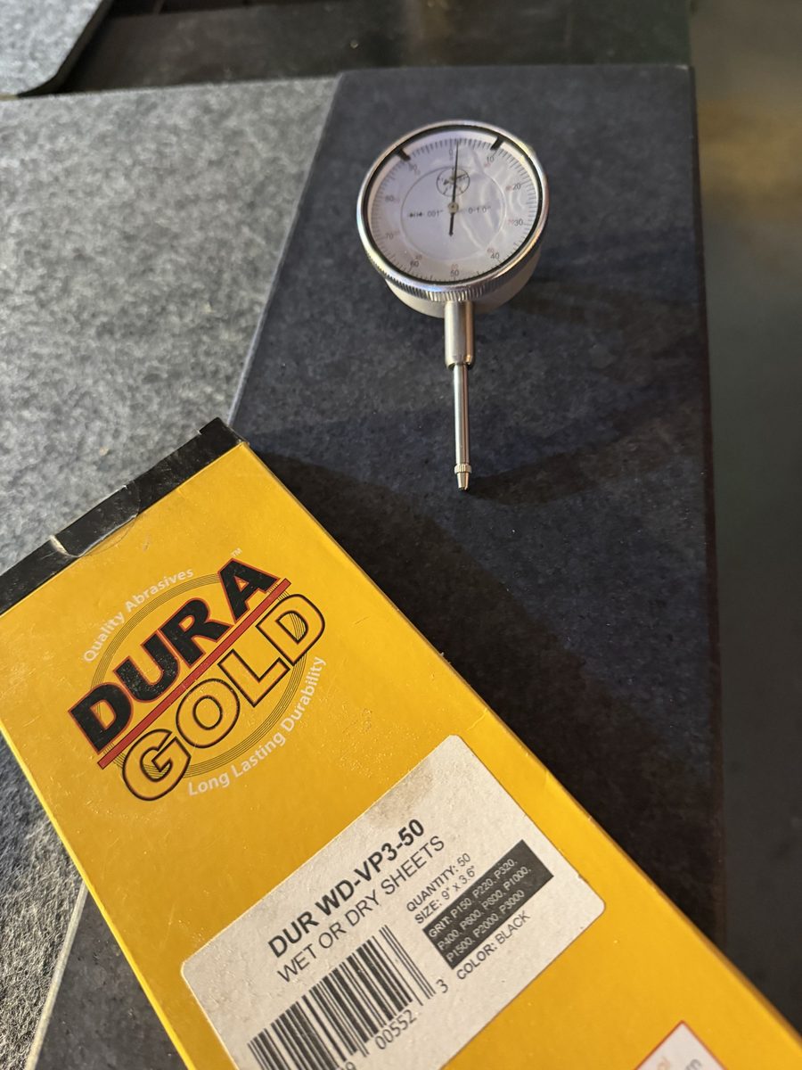
Not by looking at it, for all the reasons above. The shop keeps two granite flats: surface plates, the reference a machine shop works flat against. We lap on them, working down through the abrasive grits and finishing at 6000, and not only the heatsink's mounting surface: the transistor's flange gets the same treatment, because an interface has two sides. An indicator that reads in tenths, a ten-thousandth of an inch or about two and a half microns, then says whether the surface is flat: fine enough to see the ten microns NXP allows across an inch. The answer is a number, not an opinion.
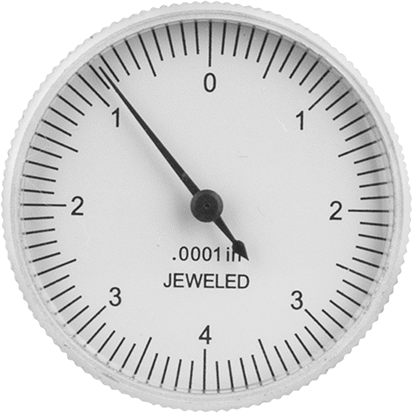
Back to Colorado for a moment: the view from the plains says flat; the survey finds the gorge. The gauge is the survey. The granite is how we take the mesas down.
The mounting is often where the story is
On one recent amplifier that came in after an LDMOS failure, the thermal compound under the failed transistor was baked on, and several of its retaining screws showed slight oxidation. Both point to a device that had been running hot. On another, our leading assessment was a junction running hot because the contact under the transistor had degraded.
So, to the customer who said it was already flat: it may well have been, to the eye. Not every heatsink needs the work. When one does, we lap the mounting surface flat, and the transistor's flange with it, before the new device goes down, so the device starts out with the thermal interface its datasheet assumes. Flat enough to look at and flat enough for a transistor are two different numbers.
“But it’s already flat!!” It is now.
The replacement LDMOS can be the expensive part of an amplifier repair, and much of how long it lasts is set by how hot its junction runs. Every degree the thermal interface gives back is service life for the device. Lapping is a small part of the job next to the part it protects, and it comes with the replacement, not as extra hours on your estimate.
The most cost-effective LDMOS are those you pay for once.
An amplifier that runs hot?
Tell us what you are seeing, and when it started.